Prototipos de PCB de forma sencilla
Servicio completo para prototipos de PCB personalizados.
9:00 - 18:00, Mon.- Fri. (GMT+8)
9:00 - 12:00, Sat. (GMT+8)
(Excepto los días festivos chinos públicos)
The Spring Festival of 2025 is coming, our "Standard PCB" factory will start the Lunar New Year holiday from Jan 27th - Jan 30th (GMT+8). PCBWay remains in partial production throughout the Chinese New Year holiday. Please arrange your orders in advance. Pls check our schedule >>
Prototipos de PCB de forma sencilla
Servicio completo para prototipos de PCB personalizados.
9:00 - 18:00, Mon.- Fri. (GMT+8)
9:00 - 12:00, Sat. (GMT+8)
(Excepto los días festivos chinos públicos)
Before assembly, factory will check assembly files. Assembly files you provided maybe not complete. Such as no designator in silkscreen, silkscreen are not complete and not clear,no orientation in silkscreen, centroid file is not complete, no pick and place file, pick and place file can not match with silkscreen and so on.
Please see more detail below. Here is the link which shows complete assembly files you need to provide.
1.No silkscreen in gerber file, no assembly drawings or pdf file,no centroid file(pick and place file)
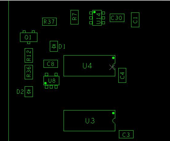
2.silkscreen drawing is too mess which can not be identified

3.No designator on silkscreen

4.Factory can not assembly when there is no designator on centroid(pick and place) file. Suggestion: please provide complete centroid files,including XY data and designator if you can.

5.Pick and place file for top and bottom side are together,which cause confusion of factory to do assembly.
Suggestion:please provide pick and place file separately for each layer, then this will be more clear for assembly.

6.No orientation instructions for polarity components. Suggestion: It it better to add “+” “-” marks or electric current orientation mark on pcb. Or note “K” is negative, or other notes which can show orientation of the components.Usually special mark side is negative in default,but special mark side in tantalum capacitor is positive. If you want to learn more, here is an article about orientation instruction of components.


Please add polarity cathode or anode mark and pin 1 in silkscreen layer.
If you do not want this information to be printed on the board, please send an individual assembly drawing file including those information to us. For cathode or anode, check the picture for reference, if use one line or one dot, we may get confused since sometimes it can be either cathode or anode. For pin 1, it’s ok to use dot.
It will be great if you have 3D images including into the Gerber file or send to us.

7.Total number of designators in Centroid file is different from what in the BOM. Some designators are included in BOM, but not in centroid file. Suggestion: 1. please verify if some designators in BOM are no need to solder 2. please confirm if the centroid file is correct?


8.Normally, we buy components follow the part number in the BOM, but the value what you wrote in BOM is not same with value in part number. Suggestion: 1. please check the value in the BOM is correct or not 2. please check the part number is correct or not

If existing different value in same designator of BOM, it is recommended to confirm the correct value and delete the wrong value, update the BOM in time to avoid errors in repeated order.

9.The quantity of designators is not same with what indicated in the BOM, cannot check how many parts should be bought. Sugestion: please check the exact quantity you want en based on the real quntity and designator, then update the BOM in time.

10.The desigantor in BOM cannot match the silkscreens on the boards. For example, designator in BOM is X2, however the silkscreen is X6. Suggestion: please correct the wrong designator in BOM.

11.In the general naming convention, C means Capacitor, R is Resistor. If the component is resistor, but you name with C, it will confuse us. If you can name capacitor with the beginning of C, resistor with the beginning of R, it will be much better.

12.In BOM, if no color requirements for LED, we cannot confirm which LED color you want. We also cannot confirm the part is right or not when the color requirements on BOM is different. Sugestion: write correct parameters in BOM like the LED color, brand, package.
13.It’s not normal the designator is repeated in BOM. If only existing one designator, it is suggested to delete the extra repeated designator OR correct the designator in BOM.
