Summary: Harmonics originate from non-linear loads in power systems. Harmonic is a current or voltage at a multiple of the power system’s fundamental frequency. This article will introduce the six techniques that are necessary for the reduction of harmonic distortion.
The earliest method of controlling problems associated with harmonics involved the use of a single-tuned filter, which offered a lower impedance path for the harmonic currents. Interestingly, finding a harmonic-producing load in the range of megavolt-ampere in industries that operate without harmonic filters is not a difficult thing. Large producers of harmonics, more so in the industry sector, may still adopt traditional harmonic filtering methods to control disturbances that arise beyond the system’s metering point and end up affecting sensitive processes and equipment. This method of filtering involves a lot of finances, and hence, it is not cost-effective for residential and commercial facilities. In this article, we are going to take a wider look at the technical techniques that can be used to control harmonics and reduce the distortion harmonics cause when the signal flows in power systems.
Network reconfiguration is one of the measures that can help reduce harmonics. This process starts by identifying the users or sectors that produce a lot of harmonic current to the power system and categorizing them according to the characteristics of the frequency content.
Suppose the use of harmonic filters is not a consideration. In that case, mixing both linear and non-linear electric loads on the feeder can reduce harmonic distortion. Linear loads work as natural attenuators, controlling the parallel peaks of the resonant.
Increasing the ratio between the present short circuit and the rated load currents means a stronger electric supply node. This is common when power suppliers increase the size of their power substations. It also happens when large power consumers, like industrial clients, add other supportive cogeneration on the main supply bus to improve peak demand during operations.
The ratio between the short circuit and the load current gives us the source stiffness of the power system. A stiff AC supply increases the chances of short-circuit current being available.
With a strong supply node, you have a better chance of absorbing transient disturbances starting.
Expect low impedance sources with high short-circuit currents, which in turn form an inverse function of the transformer's size. We can illustrate this by computing the impedance change when an old, worn-out transformer-rated MVA1 is substituted with a new transformer-rated MVA2.
By using the transformer impedance fundamental expression_,
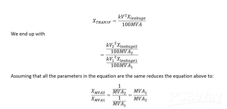
This equation gives us the impedance ratio for how the new transformer to the old transformer varies. For example, a 60-MVA transformer will give an impedance twice as small as a transformer of 30-MVA will give and increase the short-circuit by double, where the assumption is that the two transformers suffer the same leakage current problem.
At the harmonic frequency, capacitive and inductive impedances of the power system vary according to the frequency function:

Which is made of the feeder and the components of the substation.
For short feeders, the dominant component is the source impedance. In such situations, harmonic currents are expected to reach the system’s substation, creating harmonic distortion. With stiffer systems, expect smaller harmonic distortion.
Here, we can employ full-wave rectification.
The six-pulse unit is the most basic available polyphase converter. The 12-pulse unit is used to eliminate harmonics of a lower order, 5th and 7th.
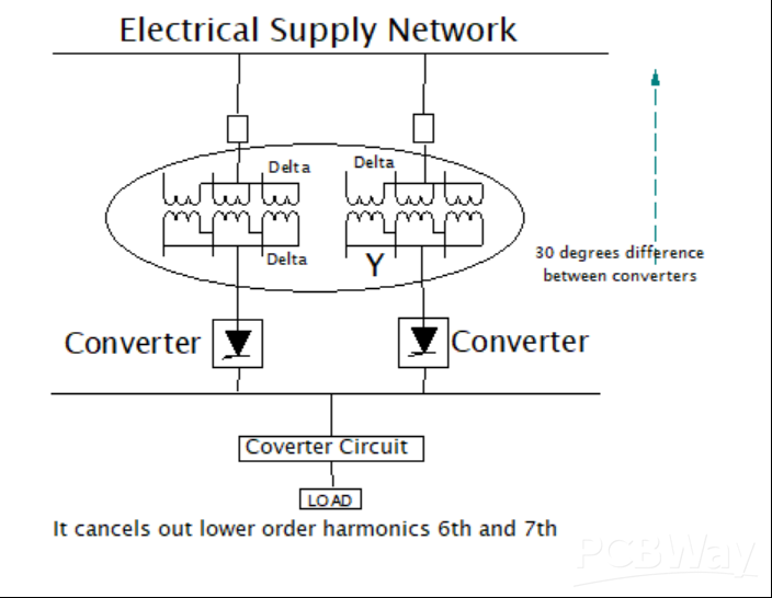
Figure 1:12-Pulse Converters Connections
If you want to reduce other harmonic currents, you carry out a phase multiplication. For example, a 24-pulse unit is constructed from a combination of four pulse full-wave rectifier bridges, each having a 15-degree phase shift compared to other rectifying units. This is made possible by utilizing phase-shifting transformers that separate the additional windings connected in a zigzag. See the figure below.
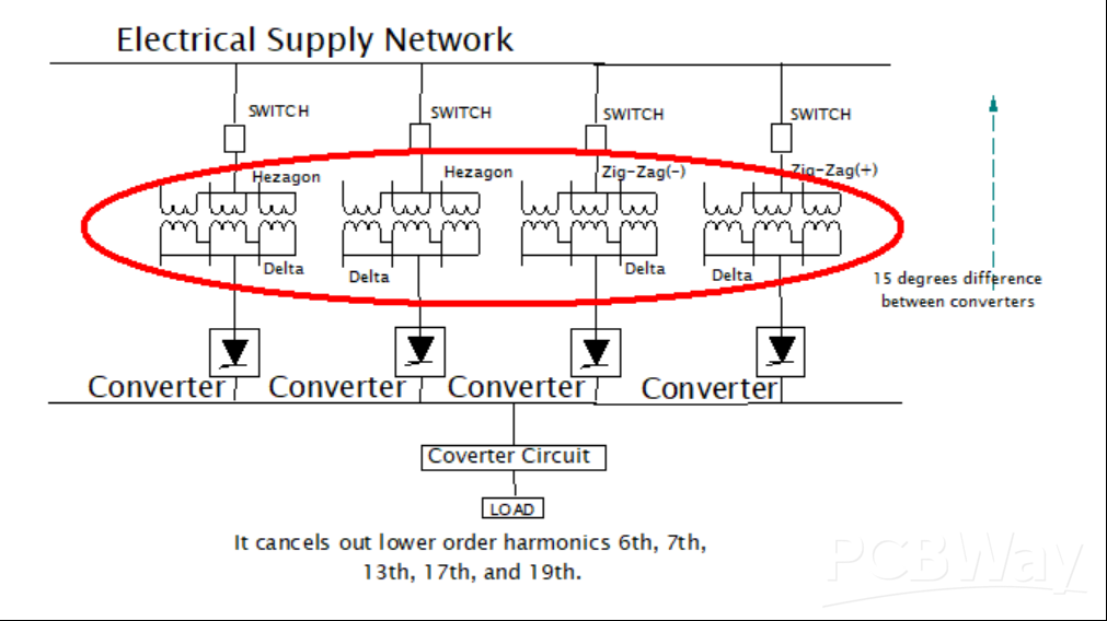
Figure 2:24-Pulse Converter Connection
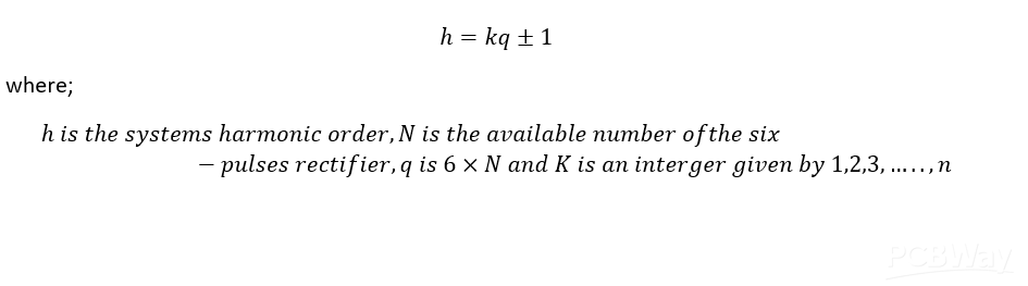
Conditions for harmonic elimination using a six-pulse rectifier follow the following approach:
The equation for the characteristic harmonic reduction can be written as.
Series reactors have long been incorporated into the control of short circuits in industries. They are used in smelting industries, power substations, and steel plants. Sometimes, series reactors are perfectly used to attenuate harmonics.
Variations in the single-phase electric loads can lead to an imbalance of current in the three-phase conductors, creating a dissimilar drop in the voltage, which in turn induces an unbalanced phase-to-phase voltage.
This unbalanced phase-to-phase voltage is very dangerous to the distribution feeder, especially when there are poor measures for compensating the lost voltage. A perfectly balanced system is hard to attain, but always try your best to balance the phases, which ends up reducing harmonics.
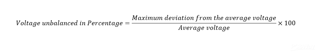
Phase Voltage Unbalance
To determine the unbalanced voltage most easily, you need to know how to calculate it.
Start by calculating the deviation using the formula below:
Too many electric networks may have nonlinear loads with dissimilar spectral content. Grouping these loads to classes with a similar harmonic spectrum helps optimize the location, installation, sizing, and selection of the harmonic filters.
The article has introduced the six techniques that engineers can employ to minimize harmonics in power systems. They include:


